Hi Ichiro Itoi,
Thanks for you answer!
I just do the model checking work. So I haven't the schematic for simulation.
Through the Ground Clamp Curve, I can see 2.4mA at 0V. Could you tell me the origin of the 2.4mA.Leakage current or the pullup resistor current ?
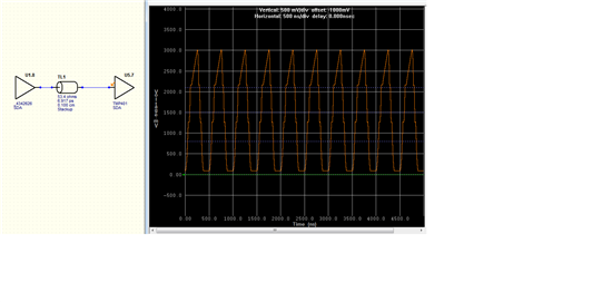
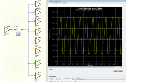
If we do the pre-simulation use the Star-topology(One Driver to 8 tmp435).
2.4mA is large enough to affect the simulation result.It will increase the bias voltage.You can see in the following picture.
One TMP435 reciever,
Eight TMP435 receiver,
Thank you very much!
Best regards,
Shen feiqin